|
Contents A Simple Homebrew
Active Antenna Testing the
Homebrew Active Antenna A Simple Homebrew Active Antenna
You don’t
need much for listening to the VLF band, only SAQrx and a simple amplifier
connected to a small probe – that what we call an active e-field antenna. If
you first want to know how this type of antenna works in general, read the notes on active antennas. We will
use an op-amp as the active element of the antenna so everything reduces to a
handful of components (see Fig. 1).
Fig. 1: The basic circuit diagram of our homebrew active
antenna This is
an amplifier with the e-field probe connected over a coupling capacity of 56
pF to the non-inverting input. A resistor with a large value (here 3.3 MOhms) ensures a high input impedance
to preserve the small voltages we get from the e-field probe. At the same time, the resistor provides a way for the
op-amp's bias current to drain. If you choose the resistor too high, the circuit may no longer work.
Together, C1 and R1 form a high pass filter with a cutoff frequency somewhere near 1 kHz. The
resistors R2 and RV1 set the gain of the amplifier, simply calculated by
their ratio: The VLF
signal leaves the circuit via the capacity C2. The value is not crucial, so
take the value you can provide. The heart
of our simple circuit is a TL071, a low noise
op-amp with JFET inputs. To be honest, the whole circuit is more an impedance
converter than an amplifier. It transforms the high impedance of the probe
connected to its high resistance input to its low-ohm output. Op-amps
are designed for using dual power supplies. If we want to use a single supply
(i. e. one 9 V battery or so), we have to add some components to generate a
virtual midpoint (R1 and R2, C4). Besides, we add C1 and C2 to achieve some
noise cancelling (RFI) on the supply lines.
Fig. 2: The complete schematic diagram for the simple active
antenna You can
build the whole thing on a breadboard or on an experimental pcb. The E-field Probe
Now we
have to connect our impedance converter circuit to the outer world, i. e. the
VLF electromagnetic field. We do this with a capacitive probe to the electric
component of the field. Phew,
sounds like an elaborate design. It is
just a metal plate with a vertical extension of 6 cm or so. Or a tinned can which can also provide
weather protection for the circuit.
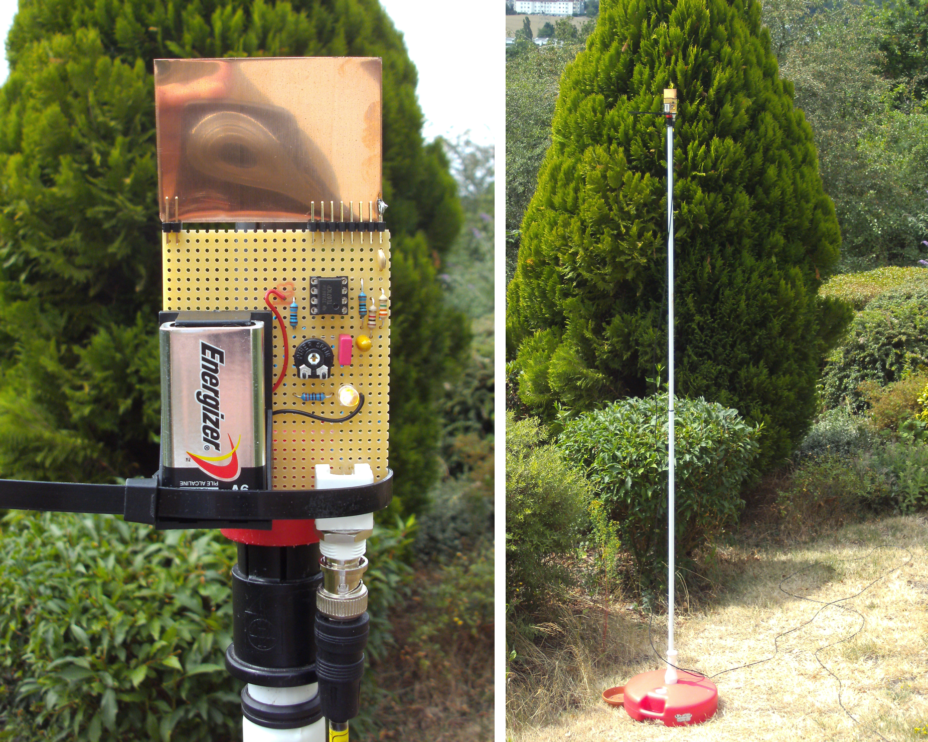
Take what you can find (see Fig. 3 for an example), solder a wire to
it and connect it to the input of the TL071.
Fig. 3: An e-field probe with a simple copper plate, mounted on a telescopic broom stick This
active antenna design is a Dünnbrettbohrer version of the PA0RDT Mini Whip antenna. Roelof, PA0RDT, uses a
copper plane of the pcb itself as e-field probe. If you decide to make a
permanent layout one day, you can do that, too. Testing the Homebrew Active Antenna
Make a
connection between the output of your active antenna and the microphone input
of your computer soundcard. Choose “System Control” / “Sound” and make sure
that the microphone input is not muted (!) and the level is not put to zero.
Then start SAQrx. Make
sure that your body is not charged electrostatically, before you try the
following! Touch something grounded first (blank parts of your radiator for
example). When you
touch the probe or the microphone input, some reaction in the SAQrx window
should occur: the baseline should move due to powerline hum or apparent peaks
should become higher. If there is no reaction, even when touching the
microphone input itself always check the sound settings of the operating
system (Windows System Control) first! With our
homebrew antenna working basically, we now must change into an environment
where power line hum and noise from switching mode power supplies, computers
and home appliances is not dominant. We have to go out. If you have an attic with windows that can be opened, go
there. For serious reception tests, the active antenna should be placed outside the house and as high as possible. So if you have attic windows, go upstairs and place your active antenna outside the window with the aid of a broom stick or a fishing rod. Allow the coaxial cable to hang down some meters in free space or lying on the roof. This is essential for a good signal to noise ratio! As another option, you can use an umbrella stand and telescopic broom stick to mount the e-field probe in your backyard/garden in at least 3 meters height. Let the coaxial cable touch the ground to get a good signal to noise ratio. Now you
should notice several navy transmitters in the SAQrx window (see Fig. 4). If you are using SAQrx
V 0.98 or higher, there should be a call sign information when you move
the mouse cursor over the apparent peaks.
Fig. 4: Lots of navy stations in the 48 kHz passband; note SAS
on 40.400 kHz, it is using the same antenna as SAQ and has to be turned down
for SAQ transmissions Improving the Active Antenna
There is
a wide field of experimenting once you have started to construct active
antennas. I am living next to Langenberg radio, a medium wave transmitter,
and I had to add a filter to prevent the medium waves to interfere with
reception. I did this using an active :-) filter. I call my
antenna design “etherprobe” aiming at the outdated concept of the ether as
medium transporting electromagnetic fields.
Have fun
improving your own design! |